Mµ128 Control

The Mµ128 page provides real-time monitoring of the device operation. It is not a measurement interface. The displayed views are informative (RMS activity, time signal, spectrum, octave bands, etc.) and are intended to verify that all microphones are operating correctly for different acquisition parameter values.
Control pages also allow real-time signal recording, according to the selected acquisition settings.
The Mµ128 control page is divided into two parts: the horizontal command menu bar at the top of the window, and the displays below.
Menu Bar
The menu bar has three sections:
- acquisition control buttons
- a status window showing current parameter states and activity
- Mµ128 controller configuration buttons
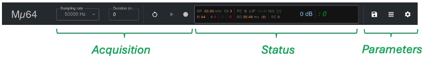
Acquisition Setup
Without changing anything else, you can immediately start acquisition and recording by using only these buttons.
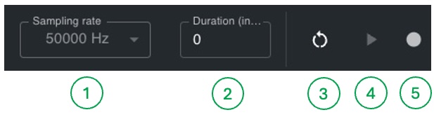
- Select sampling rate
- Select acquisition duration (
0means unlimited duration) - Full Mµ128 controller reset (use only in case of issues)
- Start acquisition
- Start recording
Start an Acquisition
You can start acquisition only if an Mµ128 controller is connected to your computer via USB.
On macOS and Windows, you must install the USB driver first (see Getting started).
If both conditions are met, the green Mµ128 controller detection icon must appear at the top of the page in the icon bar.
The acquisition start button (4) must also be active (clickable, green).
Click the acquisition start button (4). It turns into an acquisition stop button, and the counter starts running in the status bar. The MEMS RMS activity window should update according to ambient acoustic activity.
Click the acquisition stop button again. The counter stops and acquisition ends.
During acquisition, the red acquisition LED on the Mµ128 unit should light up. This LED confirms at hardware level that acquisition is running.
Record
To record an ongoing acquisition, click the record button. It turns red, indicating that data recording is in progress. Click it again to stop recording.
Recording is independent from acquisition. If you click record BEFORE acquisition starts, recording will begin only when acquisition starts. If you stop recording DURING acquisition, acquisition continues. If you stop acquisition DURING recording, recording stops automatically.
Recorded signals are always raw concentrator signals (24-bit encoded in 32-bit integers), regardless of processing applied on the control page.
Configure Acquisition
The three buttons below allow you to change acquisition and recording parameters. These parameters cannot be changed during acquisition. The buttons become non-clickable.
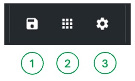
- Recording settings
- MEMS and analog channels selection
- Acquisition settings
Recording settings let you define the output directory and recording file names. If unchanged, default values are used.
By default, recording files are never overwritten. If you perform several recordings without changing the file name, the current name is reused and automatically numbered to prevent overwriting.
The MEMS and analog channels selection button opens a channel selector that lets you choose which channels to record.
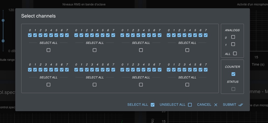
By default, all MEMS channels are selected, as well as the counter channel, but analog and status channels are not. You can change this selection as needed.
The status channel is not selectable in MµBoard versions up to and including 4.1.20.
In these same versions, the counter channel is always selected because it is used to verify data integrity.
Only selected channels are recorded during recording sequences. Note that activity from non-selected MEMS channels is not transmitted by the concentrator. Those channels therefore cannot be processed by the software.
You can close the window and discard your changes with the CANCEL button or by pressing ESCAPE.
The configuration button below opens a form for advanced acquisition settings.
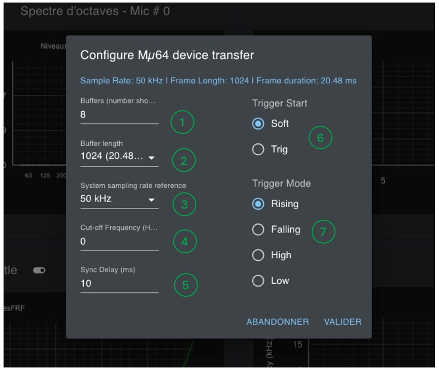
On the left side, it includes sensitive settings that, for some of them, should generally not be changed:
- Number of USB transfer buffers (default:
8) - Buffer size in number of samples (default:
1024) - Reference sampling frequency
- Spectrogram cutoff frequency
- Synchronization delay
The number of circular buffers impacts real-time USB transmission quality.
There must always be at least two buffers to ensure lossless transmission.
Higher values improve robustness against data loss, at the cost of potentially higher latency.
The default value of 8 is sufficient for standard usage (assuming the same USB bus is not heavily used by another high-bandwidth device).
Buffer size is left to the user. However, it directly impacts signal processing performed on the control page. Energy and spectrum computations are performed over this window size only. That is why the corresponding time duration (which depends on sampling frequency) is also displayed.
The reference sampling frequency must not be modified.
By default it is set to the FPGA programmed frequency.
Our systems may be configured with a 50 kHz or 48 kHz reference.
If you use 48 kHz as reference while the concentrator FPGA is programmed at 50 kHz, all software-estimated values will be scaled incorrectly.
The spectrogram cutoff frequency limits spectrum display to frequencies below this threshold. You can think of it as a low-frequency zoom. It does not affect recorded signals.
Synchronization delay should remain at its default value (10 for medium to large microphone arrays).
For very small arrays (very short cables), this value should be reduced.
Conversely, it should be increased for very large arrays.
An estimator for the optimal value will be integrated in a future MµBoard release.
Status Window
The status window displays values for the main acquisition parameters.
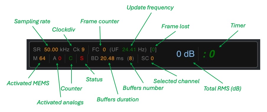
- Sampling rate: current sampling frequency
- Clockdiv: internal concentrator clock divider (used to derive the exact sampling frequency)
- Frame counter: frame counter value
- Update frequency: screen refresh frequency
- Frame lost: number of lost frames during acquisition or since the beginning of the last acquisition
- Timer: elapsed time since acquisition start (minutes and seconds)
- Activated MEMS: number of enabled MEMS channels
- Activated analogs: number of enabled analog channels
- Counter: counter channel activation state
- Status: status line activation state
- Buffers duration: buffer duration in milliseconds
- Buffers number: number of allocated transfer buffers
- TotalRMS: average power in dB across all active microphones (excluding analog channels)
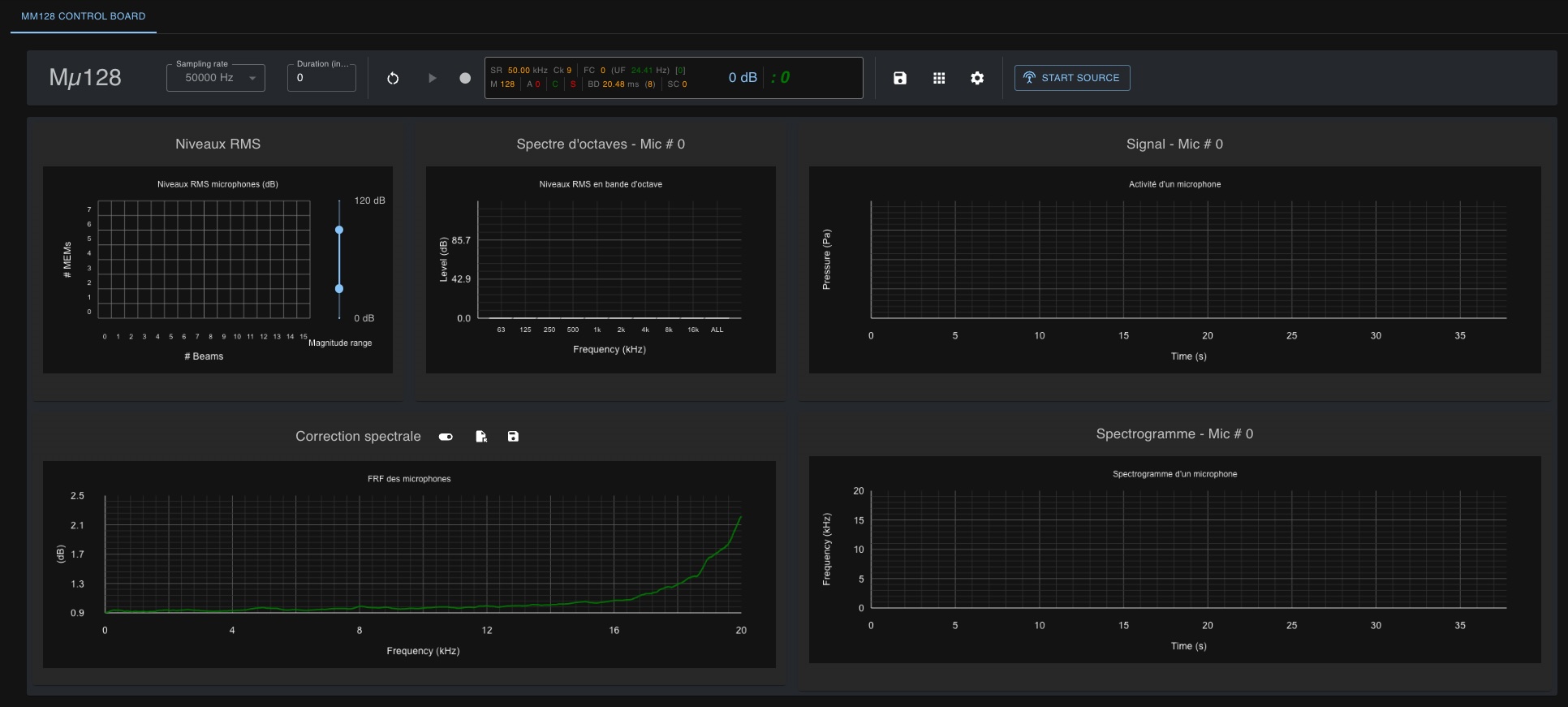
Displays
The second part of the page, below the control bar, shows a set of real-time measurements computed from concentrator signals.
RMS Levels and Selection
This window displays real-time RMS levels in dB for all MEMS channels.
The magnitude slider on the right adjusts the color scale used for power-level display.
This slider also affects the spectrogram display.
Its default lower and upper values are 30 dB and 90 dB.
To quickly check that all MEMS channels are working, set the lower slider value to 0 dB.
All active MEMS channels should then show activity.
If not, inactive MEMS channels belong to an unconnected beam, have been disabled, or are defective.
Grid cells representing MEMS activity are clickable.
If you click one cell, the selected MEMS number is shown in other window headers and in the status bar (Selected Channel - SC).
This means displayed activity in those windows corresponds to the selected MEMS.
By default, the selected MEMS is MEMS 0 (first microphone of the first beam).
Octave Spectrum
This window shows octave-band frequency analysis for the selected MEMS channel.
Signal
Activity of the selected MEMS channel. In this version of MµBoard, not all samples are displayed. For each received frame, only minimum and maximum signal values over that frame are shown.
Spectrogram
This window displays the spectrum computed as frames arrive.
As explained above, acquisition frame size is used as the FFT window size.
The spectrum is displayed from the first frequency up to the last (Fs/2).
The displayed frequency range can be changed in settings (see the settings button in the control bar).
Spectral Correction
This is the correction curve applied to the spectrogram before display.
The MEMS frequency response is approximately flat between 100 Hz and 10 kHz, but not between 10 kHz and 20 kHz.
This curve, measured in laboratory conditions on 1024 MEMS, provides the average correction required to recover an approximately flat response up to 20 kHz.
This correction is enabled by default.
You can disable it by clicking the button to the right of the window title.
The graph then switches from green to gray.
Spectral correction is not applied to recorded signals, only to the displayed spectrogram.